Schematic Capture : Wiring and Editing
Wire
The following will explain wire placement and editing.
Wires are electrical lines that connect pins to pins in a component.
Connections that are connected by wires become a Netlist.
With Quadcept, along with wiring, a wire Net Name is automatically created and merged,
and the latest status of the Net is always maintained.

* For those who want to view the video in a larger screen setting: https://youtu.be/jm9cJIa7u0A
You can confirm the Net Name by selecting a wire => [Net Name] in the [Property Window].
When you want to specify a Net Name, refer to Placing Labels.
| Wire |
| Wire is the operation for creating wires by manually specifying corners. Detailed corner specification is possible, so it is possible to execute leading according to your desire. If you want to wire quickly, use the Auto Wiring/Parallel Wire and other functions together. The following is the operation for Wire. |
|
|
|
 |
When correcting leading after wiring, Changing Wire Routing/Auto Interpolation of Wires works, so correction can be done while maintaining wire connections.
To end at the middle of a wire (wire pending), you can end by double clicking.
You can confirm wires ended in the middle using "Unconnected wire end points." in ERC .

By dragging a Pin Point such as for components and power supplies, wires can be drawn quickly, which is convenient.
Each Operation for Drawing Wires
The following will explain each operation for drawing a wire.
For wires, manual detailed corner specification is possible, so it is possible to execute leading according to your desire.
Selecting the Wire Menu
Changing the Corner Angle
Switching the Angle
Editing the Wire Line Width
Pushback Wire
Canceling a Wire
Exiting Wire Mode
Selecting the Wire Menu
Select [Create Schematic] => [Wire]
There are several other ways to perform this. Refer to About Executing Menus.
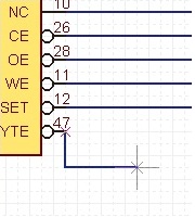
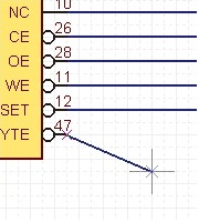
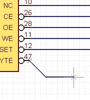
Changing the Corner Angle
The wire corner angle can be changed freely.
Wire Corner Bending Angle
| 45 degrees | 90 degrees | Free |
|
|
 |
 |
The following is the operation for changing the wire corner bending angle.
Method 1: Right click, Select => [Change the Bending Angle]
Method 2: Press "S" on the keyboard
* It can also be confirmed and changed from the Property Window.
Switching the Angle
| Before Switching | After Switching |
|
|
 |
The following is the operation for switching the angle.
Method 1: Right click, Select => [Switch Angle]
Method 2: Press "X" on the keyboard
* It can also be confirmed and changed from the Property Window.
It is also possible to determine the pulling direction by tracking using the mouse pulling direction.
| When pulling to the right side first | When pulling to the bottom first |
|
|
 |
Editing the Wire Line Width
| Editing the Line Width |
| In Wire mode, edit the wire line width. |
|
 |
|
 |
Pushback Wire
When creating a wire, you can return the corner to the previous status.
| Before Pushback | After Pushback |
|
|
 |
The following is the operation for executing pushback.
Method 1: Right click, Select => [Pushback]
Method 2: Press "Back" on the keyboard
Canceling a Wire
When creating a wire, it is possible to return to the status before drawing by canceling the wire being created.
| Before Canceling | After Canceling |
|
|
 |
The following is the operation for executing pushback.
Method 1: Right click, Select => [Cancel]
Method 2: Press "Escape" on the keyboard
Exiting Wire Mode
The following is the operation for exiting Wire mode.
When not creating a wire,
Method 1: Right click, Select => [Cancel]
Method 2: Press "Escape" on the keyboard


