PCB Layout CAD : PCB Settings
Gerber
The Gerber section of the Settings dialog allows you to specify the output layers and set up the required aperture information for Gerber generation.
For more details about opening the PCB Settings screen, refer to About PCB Settings.

| Tab Items | Content |
|
Display layer combinations for Export Gerber can be registered. |
|
|
The file format for exporting Gerbers can be set. |
|
|
It is possible to set the D code for the specified Aperture. |
Output Layer
Display layer combinations for Export Gerber can be registered.
The checks on the left toggle between Enabled/Invalid. Uncheck temporarily unnecessary items for exporting.
Example of Setting List Settings)
With TopPattern, only "Electric" of the Top Layer is exported as the display status.
For others such as TopSilk, all can be exported according to the display combination set in the Display Settings.

| Adding to the Setting List |
| The following will explain how to add to the Setting List. |
|
 |
|
 |
|
 |
| Deleting from the Setting List |
| The following will explain how to delete from the Setting List. |
|
 |
| Changing Names in the Setting List |
| The following will explain how to change names in the Setting List. |
|
 |
Show Output Layers only
When the check for "Show Output Layers only" is removed, all layers will be shown.
| When "Show Output Layers only" is checked | When "Show Output Layers only" is unchecked |
|
|
|
Present Layer Display
The Display Layer that applies to the current design drawing can be applied automatically.
This is convenient because confirmed settings displayed on the screen can be applied as they are.
Output Settings (Output Layer)

Offset X, Offset Y
These fields allows you to specify the distance by which the objects in the specified layer(s) should be moved along the X/Y axis.
| Item | Description |
|
Offset X |
Use this field to specify the distance by which the objects in the specified layer(s) should be moved along the X axis. |
|
Offset Y |
Use this field to specify the distance by which the objects in the specified layer(s) should be moved along the Y axis. |
Mirror
This control allows you to flip the layers included in the list item. Use the drop-down list to choose from the following:
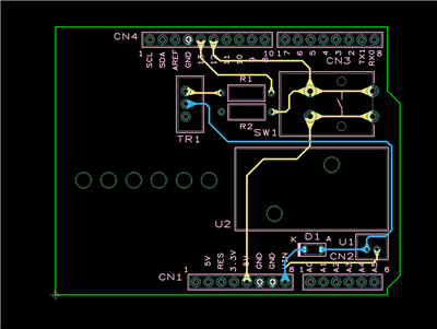
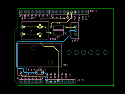
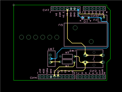
| No Mirror | Horizontal Mirror | Vertical Mirror |
|
|
The board will be flipped horizontally.
|
The board will be flipped vertically.
|
Output Settings
This tab allows you to specify the file format for Gerber generation.

Format
| Item | Content |
|
Format |
Extension Gerber (RS-274X) is fixed. |
|
Unit |
It is possible to select either "mm" or "inch". |
|
Number of Integer Digits |
The number of integer digits can be set. |
|
Decimal Places |
The decimal places can be set. |
| Zero Suppression |
It is possible to select from "None", "Reading", or "Trailing". |
|
Prefix |
The prefix at the beginning of the Export File Name can be set. |
Option
| Item | Content |
|
Omit Same Coordinates |
Enable this option to suppress equal coordinates. This allows you to reduce the size of the Geber files. |
|
Output Report File |
It is possible to set whether to output a Report File. |
|
Extension |
The Report File extension can be set. |
Report File Example)

Aperture
It is possible to set the D code for the specified Aperture.
Aperture Settings Example)
The D code has priority to be assigned as the set Aperture.

Exporting Gerbers
There are the following methods for executing Export Gerber.
- Click the  icon of the PCB Settings Gerber screen
- Open a PCB document and select the [Project] >> [Gerber] >> [Export Gerber] command.
- Batch Output
Saving Settings
Settings can be saved and read. For more details, refer to Default Environment.


