This is the window for managing layers and performing Toggle Display.
When the currently active document is a schematic, Toggle Display is executed for the comment layer,
and when it is a PCB, display and lock are toggled for each layer.
* By default, this is docked on the top-right of the screen.
|
| Layer Window for a Schematic |
Layer Window for a PCB |
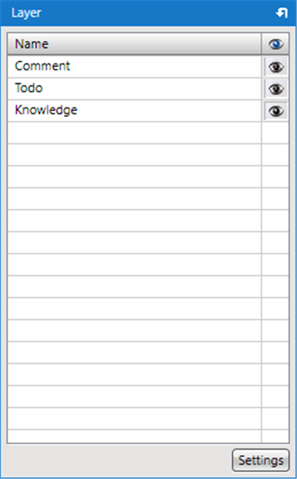 |
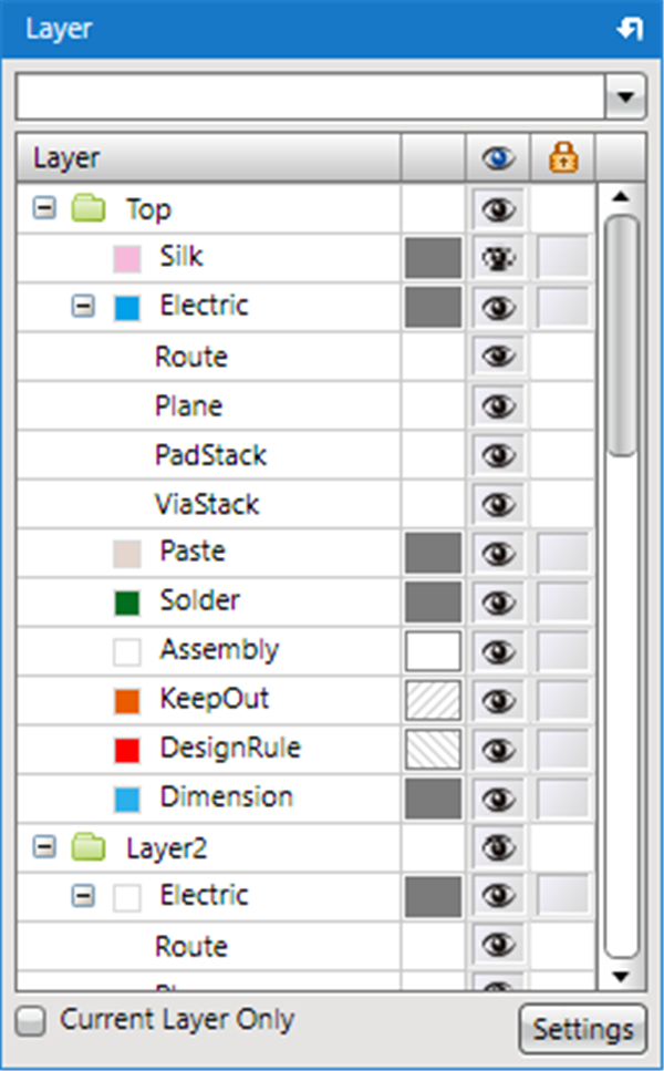
|
|
Layer Window Icon To change the Layer Settings, click the "Settings" button at the bottom of the screen.
When the Eye icon is displayed, it is in the Show status, and when it is hidden, the layer is in the Hide status.
It is possible to toggle by clicking or dragging. |
| |
Drag the Eye icon of the Layer Window. |
|
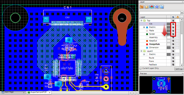 |
| |
The layer where the Eye icon is hidden will be hidden. |
|
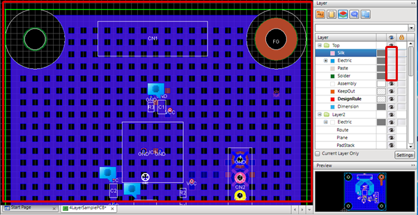 |
It is possible to change the fill style of the PCB layer, change the layer color, and to change the layer lock status.
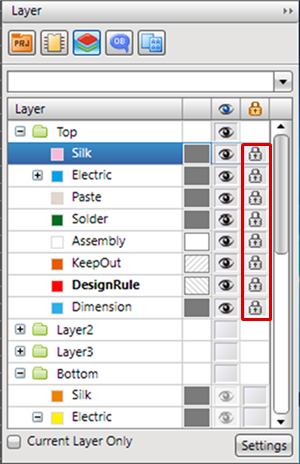
Lock means that the objects on the layer cannot be selected or moved. |
| |
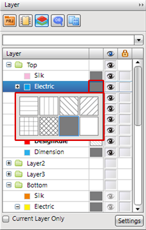
Click the Fill Style area. |
| |
The Fill Style list will be displayed, and you can change the style. |
|
 |
| |
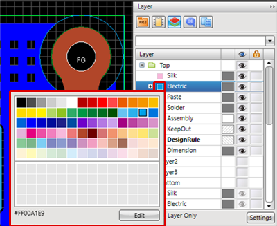
Click the Color area. |
| |
The Color Palette will be displayed, and you can change the color. |
|
 |
| |
As with the Eye icon, the lock status can be toggled by clicking or dragging. |
|
 |
For more details about batch toggling the Eye icon and Lock icon, refer to Batch Toggling ON/OFF.
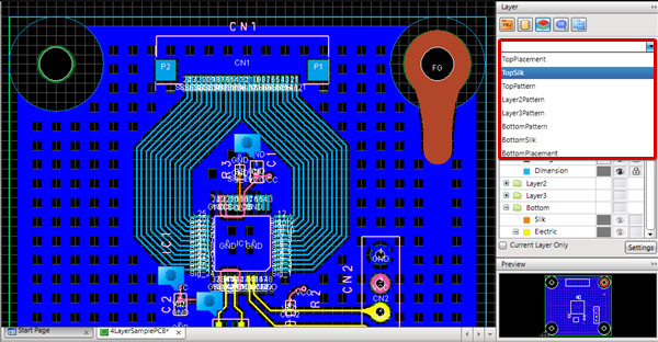
| Using the Display Layer Settings, you can easily toggle display of the PCB drawing that is being designed. |
| (1) |
From the Layer Window, select the Gerber Batch List. |
|
 |
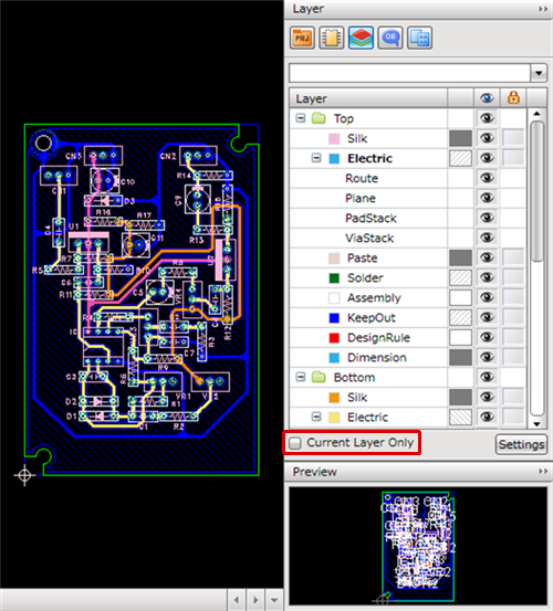
| The following will explain how to display only a current layer. |
| (1) |
Check the checkbox of "Current Layer Only". |
|
 |
| Only a current layer will be displayed. |
|
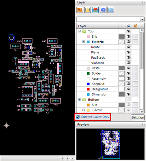 |
"Current Layer Only" will change the visibility of physical layers. "Other" and "System" layers maintain their current display status.


